Service Hotline
+1 4152729688
2023-09-21 11:25:56
Abnormal fault description Indicates the level of countermeasures
UV1 Main loop Low voltage (PUV) During operation, the main circuit voltage is lower than the Low Voltage Detection Standard (15ms, instantaneous shutdown protection 1). Check the power supply voltage and cable connection A
Dc Bus undervoltage 2S) Low voltage detection standard 200V: About 190V lower than 400V Level: less than 380V
UV2 Low voltage control circuit (CUV) control circuit voltage is lower than the low voltage detection standard 2) Check the power capacity
CTL Ps undervoltage
Precharge contactor circuit A when the UV3 internal electromagnetic contactor is faulty
MC Ansewerback
UV instantaneous power failure detection 1) Main circuit DC low voltage detection below the standard 2) precharge contactor B
Under voltage 3) The control circuit voltage is lower than the low voltage detection standard
OC Overcurrent (OC) converter output current exceeds OC standard 1) Impedance Check the insulated motor is normal A
Overcurrent 2) Extend the acceleration and deceleration time
GF Ground fault (GF) The ground current on the output side of the inverter exceeds 50% of the rated current of the inverter 1) Check whether the motor insulation deteriorates A
Grounding fault 2) The connection between the inverter and the motor is broken
OV Overvoltage (OV) The DC voltage of the main circuit is higher than the overvoltage detection standard grade 200V: about 400V Grade 400V: For deceleration time, install brake controller and brake resistor A
800V overvoltage
SC Load Short circuit (SC) Insulation and impedance converter output short circuit Check that the motor is normal A
Short circuit
PUF fuse (FI) 1) Main circuit crystal module is faulty 2) DC circuit fuse 1) Check whether crystal module A is normal
DC Bus Fuse open 2) Check whether the load side is short-circuited and connect to the crust
OH heat sink Overheat (OH1) The fan temperature of the crystal oscillator module exceeds the threshold Check whether the fan functions properly and is within the nominal temperature range A
Heat sink Over TMP
OL1 Motor Overload (OL1) The output current exceeds the motor overload capacity to reduce load A
Motor overload
OL2 Inverter load (OL2) Inverter output current exceeds 150% of rated current value 1 minute to reduce load and extend acceleration timeA
In item 1) overload under the input power converter
PF Input 2) Three-phase input voltage imbalance 1) Check whether the power supply voltage is normal A
Inut Pha Loss 2) Check whether the input end screw is locked
LF output under the phase of the power supply on the output side of the inverter 1) Check whether the output end screws and wiring are normal A
Output Pha Loss 2) Three-phase impedance check of the motor
RR brake triode inverter repair abnormal brake action poor A
Dyn Brk Tansisr
RH Brake controller Overheat brake controller temperature is higher than allowable Check brake time and brake resistance A usage
Dyn Brk Resistor
OS Speed (OS) The motor speed exceeds the speed standard (F1-08) A
Overspeed Det
PGO PG (PGO) PG Break wire (PGO) 1) Check the PG connection 2) Check whether the motor shaft is A
PG open circuit
DEV Speed deviation is too large (DEV) Command speed and speed feedback value is greater than the deviation rate (F1-10) Check B overload
Velocity deviation
EF whether the reverse and reverse commands exist at the same time for more than 0.5 seconds. The positive and negative commands cannot exist at the same time as B
External fault
EF3-EF8 terminal 3 External abnormal signal Input External terminal 3-8 Abnormal signal input 1) The abnormal signal input terminal of A is U1-10
External Fault3-8 EF4-EF8-terminal 4-8 Identification 2) Repair the terminal according to the abnormal condition
OPE 01 Frequency converter Capacity setting Abnormal frequency converter capacity parameter 902-04) Set reverse adjustment set value C
OPE02 Limit Parameter setting correct If the parameter exceeds the limit value Adjust the set value C setting
Abnormal fault description Indicates the level of countermeasures
OPE 03 terminal multi-function input set H1-(01-06) Improper set value not set in order of size or repeat the same value to adjust the set value C setting
OPE 10 v/f parameter inappropriate E1-(04-10) The following conditions must be met: Large Fmax is equal to (E1-04) FA (E1-06) The adjusted setting value is greater than C
V/f Ptrn Settings FB (E1-07) Fmin (or E1-09)
OPE11 Parameter setting value 1) C6-01 is greater than 5KHz but C6-02 is equal to 5KHz Adjust the setting value C
Carr frq/on-Delay 2) C6-03 is greater than 6 but C6-02 is equal to C6-01
ERR EEPROM input error Parameter initialization is correct. Information cannot be written to the EEPROM control panel. Replace B
EEPROM/Rlw Err
CALL SI-B transmission error Power input control signal abnormal transmission machine control signal from new C test
Serial Com Call
ED transmission fault control signal sent after 2 seconds did not receive from the new A test
Memobus Com Err normal response signal transmitter control signal
CPF00 Control loop transmission is abnormal 1 The connection between the manipulator and the control board is abnormal 5 seconds after power input A Install a new digital display operator to check the control loop
COM-ERR (OP
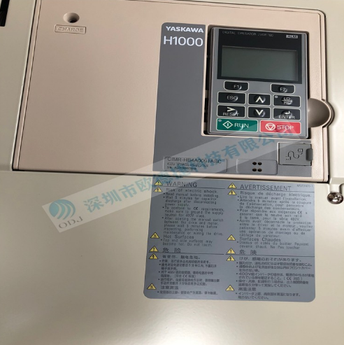
The above content is the meaning of Yaskawa inverter fault code, which can basically solve everyone's problems. This article is provided by Shenzhen Oudejie Technology Co., LTD., the company specializes in the sale of imported Yaskawa inverter, and promises to sell products are new imported, while providing customers with quotation, selection, product information and other services.
